Lab Facilities

List of laboratories

  • Fluid mechanics and Fluid machinery
  • Material testing and Metallurgy
  • Manufacturing process
  • Thermal Engineering
  • Dynamics of machinery
  • Mechanical measurements and metrology
  • CAD and CAM
  • Basic workshop

Fluid Mechanics And Fluid Machinery Laboratory

This lab has basic fluid mechanics and hydraulic machinery set-up. This lab is equipped with different flow measuring set-ups for fluid mechanics such as venturi meter, orifice meter, notch, weir and different pump set-ups for hydraulic machinery where students can visualize the basic theory of working flow meters and pumps.

Objectives

  • To compare the results of analytical models introduced in lecture to the actual behavior of real fluid flows.
  • To discuss and practice standard measurement techniques of fluid mechanics and their applications.
  • To work on small design projects.
  • Read and follow directions for laboratory experiments.
  • Operate fluid flow equipment and instrumentation.
  • Collect and analyze data using fluid mechanics principles and experimentation methods.
  • Prepare reports following accepted writing and graphical techniques.
  • Perform exercises in small teams.
  • Demonstrate principles discussed in Fluid Mechanics lecture course.
  • Demonstrate appropriate work habits consistent with industry standards.

Scope

  • To learn the basic concepts of fluids properties and rate of flow.
  • To determine the efficiency of different types of pumps and turbines.
  • To study different types of impellers used in pumps.
  • To find out the rate of flow of the fluid and also find out the coefficient of discharge
  • To find out the frictional resistance of the given set of pipes.
  • To find the maximum efficiency of the pump as well as turbine with different input and head etc.

Fluid Mechanics

List of experiments/Exercises

  • Determination of Metacentric height of a buoy
  • Determination of force due to impact of jets
  • Determination of co-efficient of discharge of venture meter
  • Determination of co-efficient of discharge of orifice meter
  • Determination of co-efficient of discharge of orifice by (a) constant head method and (b) variable head method
  • Determination of co-efficient of discharge in mouth piece by (a) constant head method and (b) variable head method
  • Determination of major losses in pipe flow
  • Determination of minor losses in pipe flow
  • Measuring discharge using V notch
  • Measuring discharge using rectangular weir

Fluid Machinery

List of experiments/Exercises

Study and performance test of the following hydraulic machines

  • Centrifugal Pump
  • Self-Priming Pump
  • Reciprocating Pump
  • Jet – Pump
  • Submersible Pump
  • Vertical Turbine Pump
  • Parallel & Series Pump
  • Gear Pump
  • Vacuum Pump
  • Pelton Wheel Turbine
  • Francis Turbine
  • Kaplan Turbine

List of equipments

  • Pelton Turbine
  • Francis Turbine
  • Centrifugal pump
  • Submersible pump
  • Reciprocating pump
  • Venturimeter apparatus
  • Orifice and mouthpiece apparatus
  • Orifice meter apparatus
  • Pipe friction apparatus (major loss )
  • Losses in pipe line apparatus(minor loss)
  • Impact of jet apparatus
  • Closed circuit self-priming pump
  • Closed circuit jet pump
  • Closed circuit gear oil pump test rig
  • Closed circuit deep well vertical turbine pump test rig
  • Closed circuit / single stage /multi speed/centrifugal/ pump test rig for series (2 stage) and parallel operation
  • Closed circuit Notch tank apparatus (Combined unit)

Material Testing And Metallurgy Laboratory

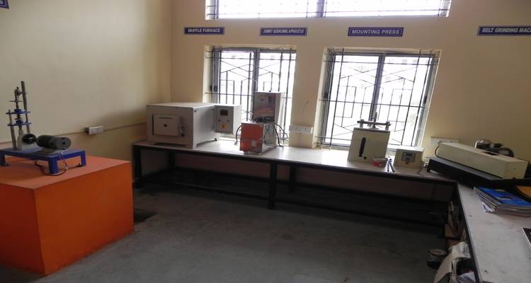
The primary focus of the Metallurgical and Materials lab is to provide with a fundamental knowledge-base associated with materials-processing, their properties, and their selection and application. Upon graduation, students would have acquired and developed the necessary background and skills for successful careers in the materials-related industries.

Objectives

  • The objective of the Material testing and Metallurgy program is to impart a fundamental knowledge of materials, properties, selection and application.
  • Study, measure and understand the properties of materials required for various applications.
  • Study and understand the fundamental structure of materials.
  • Combine a thorough understanding of these areas to perform as a Materials and Metallurgical Engineer for a wide spectrum of industries.

Scope

  • To make existing material better and invent new phenomena, material device and its applications.
  • A thorough knowledge of material science and engineering will make the students as a better designer.
  • Students can discover the ways to control the material properties through microstructure analysis.

Materials Testing Laboratory

List of Experiments/Exercises

  • Tension test – metals and composites
  • Compression Test – metals and composites
  • Hardness test : Rockwell and Brinell
  • Ductility test : Sheet metals (Al, GI and MS)
  • Impact Test

Metallurgy Laboratory

List of Experiments/Exercises

  • Study of microstructure in metals
  • Specimen preparation & microscopic study of ferrous/nonferrous metals
  • Effect of heat treatments viz.,Annealing and hardening on ferrous/nonferrous metals
  • Study of various quenching mediums
  • Jominy end quenching test

List of Equipments

  • Universal Testing machine-40T
  • Mechanical Extensometer
  • Torsion Testing Machine 100Nm
  • Brinell Hardness Testing Machine
  • Rockwell Hardness Testing Machine
  • Impact Testing Machine
  • Erichsen Cupping Testing Machine
  • 180 Bend Test Attachment
  • Bending test on beams
  • Electronic Spring testing machine( 50 kg capacity)
  • Closed circuit Notch tank apparatus (Combined unit)
  • Inverted Trinocular Metallurgical Microscope
  • Co-axial Trinocular Research Metallurgical Microscope (Model Vision Plus 5000 TM)
  • Jominy end quench apparatus
  • Disc polishing machine
  • Mounting press
  • Belt girding machine

Manufacturing Processes Laboratory

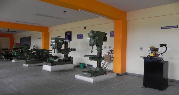
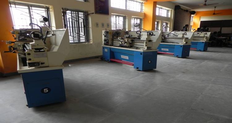
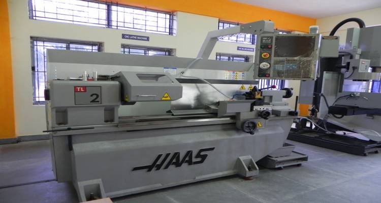
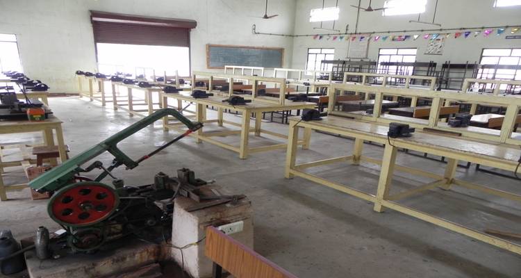
The Manufacturing Processes (MP) Laboratory is dedicated to support advancement of manufacturing research, manufacturing education that will influence, attract and develop the future manufacturing workforce. This Lab provides students with an opportunity to study and practice manufacturing processes. This laboratory offers students with experiential learning of the nature and technique of manufacturing processes. Students learning knowledge from this lab is integrated with prior and subsequent learning of other engineering topics such as engineering materials and quality planning and control. The Manufacturing Processes Laboratory includes facilities to demonstrate and explore examples of casting, molding, and machining processes. The laboratory includes a variety of instruments for measurement of process variables and product quality variables. CNC lab is equiped with a state of art technology CNC machine. It is a production machine.

Objectives

  • The overall objective of the lab is to gain a practical understanding of various manufacturing processes in hands-on environment.
  • Set-up and conduct engineering experiments related to various manufacturing processes.
  • Maintain lab manual in an engineering format.
  • Enhance ability to determine the data given and the informations to be find out.
  • Learn to make engineering judgments.
  • Extend basic knowledge to solve manufacturing process related problems.
  • Analyze date from experiments to performe and reach conclusions.
  • Improve team working skills through group assignments

Scope

  • To Study the lathe machine, lathe tools cutting speed, feed and depth of cut.
  • To perform step turning, knurling and chamfering on lathe machine as per drawing.
  • To study shaper machine, its mechanism and calculate quick return ratio.
  • To cut multi-start square/metric threads/li>
  • To Study the milling machine, milling cutters, indexing heads and indexing methods. Prepare a gear on milling machine.
  • Study the characteristic features of Drilling machine.
  • To drill and tap holes on a metal plate and investigate the accuracy of tapping holes.
  • Moulding Sands, constituents and characteristics.
  • Preparation of mould using solid and split pattern.
  • Study of single point cutting tool geometry & grind the tool as per given tool geometry.
  • Study the hobbing machine, hob cutters. Prepare a helical gear on hobbing machine.
  • Study of cylindrical grinding machine, grinding wheel, cutting speed, feed and depth of cut.
  • Study of CNC systems. Prepare a programme on CNC machine for any one type of operation on lathe and milling machine.

Manufacturing Process Laboratory-I

List of experiments/Exercises:

Turning

  • Study of Lathe
  • Plain turning and facing
  • Step turning, Grooving and Chamfering
  • Taper turning by swiveling compound rest method
  • Taper turning by attachment method
  • Thread cutting

Shaping

  • Study of Shaper
  • Cube shaping
  • Step shaping

Milling

  • Study of Milling Machine
  • Cube Milling
  • Step Milling

Manufacturing Process Lab-II

List of experiments/Exercises

  • Drilling and Boring
  • Turning between centers
  • Drilling and Tapping
  • Square and multi start thread cutting
  • Eccentric turning
  • Shaping and V-slot grooving
  • Study of Grinding machine
  • Cylindrical grinding operation
  • Spline Milling
  • Keyway milling

Manufacturing Process Lab-III

List of experiments/Exercises

  • Study of Foundry tools
  • Mould preparation using solid- patterns
  • Mould preparation using split- patterns

Gear Cutting

  • Helical gear milling
  • Study of gear hobbing machine
  • Spur gear hobbing

Tool Grinding

  • Study of tool and cutter grinder
  • Grinding of single point cutting tool

CNC Programming

  • Study of CNC turning and milling machines
  • Programming and TPG of CNC turning
  • Programming and TPG of CNC milling

List of Machines

  • UNITECHall Geared Lathe
  • Shaping Machine
  • Rubber Pad
  • Radial Drilling Machine
  • Pillar Drilling Machine
  • Universal Milling Machine
  • Cylindrical Grinder (Indian Make “Master” Model)
  • Surface Grinder (Indian Make “Master” Model)
  • Tool and Cutter Grinder (Indian make “Master” Model)
  • Gear Hobbing Machine (Indian make “Master” Model)
  • CNC Lathe Model (HASSUSA TL -2)
  • CNC Milling Model(HASSUSA TM-1)

With Stabilizer and Air Compressor

Thermal Engineering Laboratory

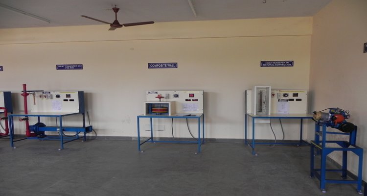
Thermal engineering is a branch of science that covers energy conversion from one form to another, working of IC engines, modes of heat transfer, principles of refrigeration and air conditioning etc. The field of thermal engineering includes a lot of applications that can be classified as the combination of thermodynamics and heat transfer, such as IC engines, air conditioning and refrigeration systems.

The objective of this laboratory is to provide the student a good environment to understand the important concepts and applications in the field of IC Engines , refrigeration and heat transfer. These concepts are necessary to understand how the typical thermal devices work (refrigerators, air conditioning devices, engines).

These fundamentals will be used to link the phenomenological processes taking place in the engine for issues of: power generation, emissions and environmental impact, fuel economy and fuel composition effects on engine operation and mechanical limitations of obtaining ideal performance.

Thermal Engineering Laboratory – I

List of experiments/Exercises

  • Determination of Kinematic Viscosity using Redwood viscometer
  • Determination of Flash and Fire Points using Cleaveland Apparatus.
  • Determination of Calorific value of Solid Fuel using Bomb Calorimeter
  • Determination of Calorific value of Gaseous Fuel using Junker’s Gas Calorimeter
  • Performance test on Reciprocating Air Compressor
  • Performance test on Centrifugal Air Blower
  • Study on the composition of Exhaust gas of an IC engine using OrsatAppratus under various loads.
  • Determination of Thermal Resistance and Conductivity of a Composite Wall
  • Heat Transfer from Cylindrical Surface by Natural Convection
  • Heat Transfer from Cylindrical Surface by Forced Convection
  • Heat Transfer from Pin Fin by Forced Convection
  • Performance of Parallel Flow/Counter Flow Heat Exchanger

Thermal Engineering Laboratory – II

List of experiments/Exercises

  • Valve and port timing diagrams of 4 stroke and 2 stroke IC engines respectively
  • Tests on single cylinder pertrol engine
    • Load test
    • finding air-fuel ratio
  • Tests on multi-cylinder petrol engine
    • Load test
    • Morse test
    • heat balance test
  • Tests on single cylinder 4 stroke diesel engine
    • Load test
    • Finding air-fuel ratio
    • Retardation test
  • Test on multi-cylinder diesel engine
    • Load test
    • Heat balance test
  • Engine exhausts gas analysis using Gas analyzer/ Gas Chromatograph
  • Performance test on cooling tower.
  • Performance test on refrigeration system
  • Performance test on air-conditioning system.
  • Performance test on a boiler.
  • Performance test on steam turbine.
  • Determination of dryness fraction of steam using calorimeter

List of Equipments

  • 2 Stage 2 cylinder air compressor test rig (swinging field type)
  • Variable speed air blower test rig
  • Air conditioning test rig
  • Refrigeration test rig
  • Cooling tower
  • Redwood Viscometer
  • Cleave land Apparatus
  • Bomb Calorimeter
  • Junker’s Gas Calorimeter
  • Composite Wall
  • Natural Convection
  • Forced Convection
  • Pin Fin by Forced Convection
  • Parallel Flow and Counter Heat Exchanger
  • ORSAT Apparatus
  • Valve Timing Diagram for 4 Stroke Diesel Engine
  • Port Timing Diagram for 2 Stroke Petrol Engine
  • Single Cylinder Four-Stroke Petrol Engine with Electrical Loading Dynamometer
  • Four Stroke Single Cylinder Diesel Engine 5 Hp KIRLOSKAR with Mechanical Break Test Rig
  • Four Stroke Twin Cylinder Diesel Engine with Electrical Loading Water Rheostat Test Rig

Dynamics Of Machinery Laboratory

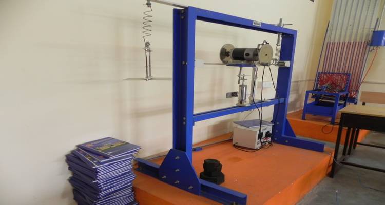
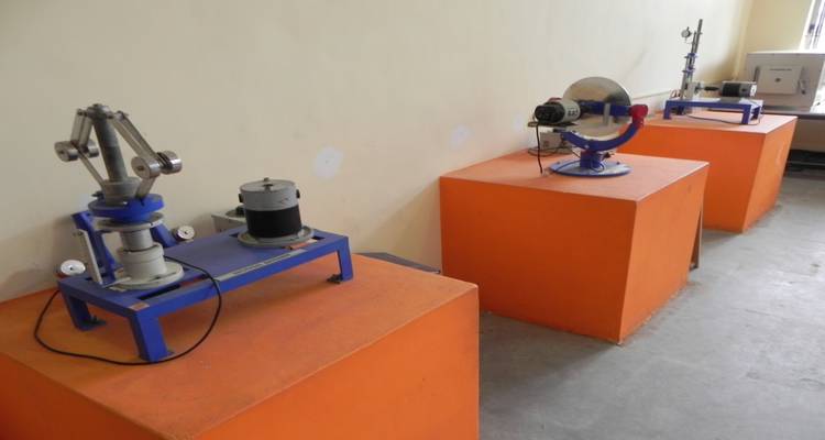
Dynamics of Machinery lab imparts practical knowledge on design and analysis of mechanisms for the specified type of motion in a machine. With the study of rigid motion bodies and forces for the transmission systems, machine kinematics and dynamics can be well understood.

Demonstration exercises are provided with wide varieties of transmission element models to understand machine kinematics. Various experiments with governors, gyroscopes, balancing machines and universal vibration facilities are available to understand machine dynamics.

Objectives

  • Measure forces due to dynamic imbalance of a rotating shaft.
  • Analyze and compute link forces in moving linkage mechanisms.
  • 3 Design a flywheel for a machine.
  • Analyze shaking forces in single and multi-cylinder engines.
  • Understand the influence of shaking forces on engine design.

Scope

  • To study inversion of four bar chain.
  • To determine moment of inertia of the given object using connecting rod.
  • Measure forces due to dynamic imbalance of a rotating shaft.
  • To determine the various types of vibration effect on the shaft.
  • To determine damping co-efficient of given systems.
  • To determine moment of inertia of the given object using Trifler suspension.

List of Experiments /Exercises

  • Demonstration of four bar inversion mechanism
  • Natural frequency of single mass, single helical spring system.
  • Natural frequency of combination of springs – springs in parallel, springs in series
  • Natural frequency of undamped torsional single rotor, double rotor system. Effect of inertia (I) and stiffness (kt).
  • Determination of radius of gyration of a given compound pendulum
  • Determination of radius of gyration, moment of inertia – bifilar suspension method – trifilar suspension method
  • Damping coefficient of torsional single rotor system – Effect on depth of immersion in oil and damping ratio
  • Resonance frequency of equivalent spring mass system – undamped and damped condition. To plot amplitude Vs frequency graph for different damping.
  • Determination of characteristic curves of Watt, Porter, Proell and spring loaded governors.
  • Static and Dynamic balancing.
  • Whirling of shafts/ determination of critical speed with and without Rotors.
  • Gyroscopic couple verification.
  • Journal bearing – pressure distribution of different loads at different Speeds.
  • Cam motion analysis.
  • Generation of involute gear profile.
  • Tracing of coupler curves.
  • Determination of error in straight line drawn by watt chain mechanism.

List of Equipments

  • 2 Stage 2 cylinder air compressor test rig (swinging field type)
  • VibrationSetup
  • Universal Governor Apparatus
  • Static & Dynamic Balancing Apparatus
  • Whirling of Shaft Apparatus
  • Journal Bearing Apparatus
  • Cam Analysis Apparatus
  • Motorized Gyroscope
  • Generation of Involute Gear Tooth Profile

List of Equipments

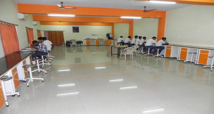
This is the laboratory where the student learns to use and calibrate measuring instruments and equipments. Main equipments in which students gain hands on experience are transducers, profile projector, sine bar, floating carriage micrometer, temperature measurement setup, force measurement setup and torque measurement setup.

Objectives

  • Understand the principle of operation and calibration of an instrument.
  • Know different measuring device for a particular application.
  • Understanding the concepts of limits, fits and tolerance.
  • Understand various testing tools for checking the alignment of machine tools.
  • 5 Understand the various transducers and application of strain gauges.
  • Understand the different devices used to measure force, torque, and pressure
  • Understand the different devices used to measure Speed, Flow, and Temperature

Scope

  • The course is intended to provide students with general knowledge about mechanical measurements and metrology laboratory techniques for industrial applications and diagnostics.
  • Ability to identify the different types of simple linear measurement instruments, design, sensitivity and use as a practical application of what they have studied in the lecture. Practice measuring some products dimensions using these instruments.
  • This lab provides the students an active learning environment for the measurement technologies used in production engineering field.
  • Students use the laboratory to collect and analyze measurement data, evaluate measurement methodologies, and learn the pros and cons of measurement technologies

List of Experiments /Exercises

  • Calibration of Micrometer.
  • Measurement of taper using Sine Bar.
  • Calibration of Plain Plug Gauge.
  • Straightness and Flatness Measurement using Autocollimator.
  • Surface Roughness Measurement (Talysurf method)
  • Inspection of Screw Threads (Effective Diameter).
  • Calibration of Inclined Tube Manometer.
  • Measurement of Pressure using Strain Gauges.
  • Determination of the Time Constant of Thermocouples.
  • Measurement of Force using Transducers.
  • Measurement of Strain using Strain Gauges.
  • Study of Displacement using LVDT and RVDT.
  • Vibration Measurement using Accelerometer.
  • Measurement of speed using stroboscope
  • Inspection of gear tooth profile using profile projectors
  • Tool Maker Microscope (inspection of screws)
  • Inspection of internal and external surfaces (C M M)

List of Equipments

  • Micrometers
  • Sine bar
  • Different plug gauges
  • Autocollimator
  • Setup to measure surface roughness
  • Setup and accessories to inspect screw threads using effective diameter method
  • Profile projector to inspect gear tooth.
  • Tool Maker microscope
  • CMM
  • Setup to calibrate inclined tube manometer
  • Experimental setup for measuring force using transducers
  • Setup to measure pressure using strain gauges
  • Determination of time constant of thermocouple temperature measuring system
  • Stroboscope set up to measure speed
  • Setup to measure strain using strain gauges
  • LVDT for displacement measurement
  • Setup to measure vibration using accelerometer

CAD / Camlaboratory

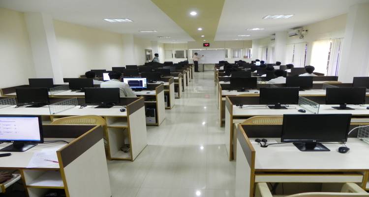
CAD/CAM Lab was established for concept design and product realization. This lab is to primarily facilitate students to evolve concepts and convert it into a complete product. The process of design, simulation and prototyping takes place in a digitally integrated environment. The facility has been designed and structured to take care of professional certification programs for students, consultancy for industries and to also carry out globally outstanding research.

Objectives

  • To revise the fundamentals of stress analysis and vibration analysis.
  • To lay a strong foundation for design analysis.
  • To be able to understand and handle design problems in a systematic manner
  • To gain practical experience in handling 2D drafting and 3D modeling software systems.
  • To be able to apply CAD in real life applications
  • To understand the concepts G and M code and manual part programming.
  • To expose students to modern control systems (Fanuc, Siemens etc…)
  • To know the applications of various CNC machines.
  • To expose the students to modern CNC application machines EDM, EDM wire cut and rapid prototyping

Scope

  • Analysis of Stress: State of stress at a point, stress components on an arbitrary plane, principal stresses, Mohr’s circle, plane stress, differential equations of equilibrium, boundary conditions.
  • Analysis of Strain: State of strain at a point, dilation, plane strain, compatibility conditions
  • Stress-Strain Relations: Generalizes Hooke’s Law, relations between elastic constants, displacement equations of equilibrium.
  • Theories of Failure: Theory of dislocations, Maximum principal stress theory, maximum shear stress theory, maximum elastic strain theory, octahedral shearing stress theory, distortion energy theory, Mohr’s theory, significance of theory of failure, use of factor of safety in design, selection of materials for engineering applications.
  • Energy Methods: Elastic strain energy, Maxwell-Betti-Rayleigh reciprocal theorem, Castigliano’s theorems, strain energy due to axial force, shear force, torsion, bending moment, theory of virtual work.
  • Axisymmetric Problems: Thick-walled cylinders, shrink fits, rotating discs.
  • Dynamic Analysis: Review of mechanical vibrations; Properties of eigen-values and eigenvectors, problem formulation for longitudinal, torsional and lateral vibrations.

Computer Aided Machine Drawing

Preparation of Drawings for Parts and Assembly of the following by using AutoCAD

  • Joints : Riveted Joints – Butt & Lap joints, Knuckle joint,
  • Couplings : flexible type flange coupling, Universal coupling.
  • Bearing : Pedestal bearing.
  • Screw jack
  • Connecting rod
  • Tail stock
  • Steam Stop valve
  • Ramsbottom Safety Valve

Computer aided design of machine components:

  • Transmission shafts,
  • Journal bearings,
  • Flange couplings etc.
  • Using solvers namely TK SOLVER (Ref: “Machine Design: An integrated approach”, Norton, R. L. 2nd Ed., Pearson Education Asia, 2001, appendix F, p.no:1001.) And
  • Autolisp[Minimum of three exercises using TK SOLVER and two exercises using Autolisp.]

PART-B

  1. Generation of Auto lisp file to draw the orthographic views of a given isometric diagram.
  2. 3D Modeling
    • Introduction to 3-D modeling – sketcher, part design, assembly and drafting workbenches
    • Generation of various 3D Models through Protrusion, revolve, shell sweep. Creation of various features. Study of parent child relationships. Feature based and Boolean based modeling surfaces.
    • Assembly modelling of components having a minimum of six machine elements. [Minimum of two exercises in part modelling and one exercise in assembly] (Use of ANY ONE of these packages such as CATIA, ProE, SOLIDWORKS, IDEAS is recommended)
  3. FE Analysis:Using any FEA software packages like ANSYS / NISA etc., solve for
    • Plane Stress Analysis on Plate with Central hole
    • SF and BMD diagrams for all kinds of beams
    • 1-D heat transfer analysis of a simple plate. [Minimum of three exercises]

HP Nodes

HP DX2480 Desktop

  • Intel Core 2 Duo Processor(2.80 GHz, 1066 MHz FSB)
  • Intel Chipset Board
  • 1 GB DDR2 RAM
  • 160 GB SATA HDD
  • HP USB Keyboard
  • HP Optical USB Scroll Mouse
  • HP Optical USB Scroll Mouse
  • HP 18.5″ Wide TFT Monitor

HP Server

HP Proliant ML 350 G6

  • Intel Xeon Processor 2.00 Ghz
  • Intel Chipset Board
  • 2 GB DDR2 RAM
  • HP 500 GB HDD RAID (250X2)
  • DVD ROM DRIVE
  • HP P Keyboard
  • HP Mouse
  • HP 18.5 TFT Monitor

HP Nodes

HP DX2480 Desktop

  • Intel Core 2 Duo Processor
  • (2.80 GHz, 1066 MHz FSB)
  • Intel Chipset Board
  • 1 GB DDR2 RAM
  • 160 GB SATA HDD
  • HP USB Keyboard
  • HP Optical USB Scroll Mouse
  • HP 18.5″Wide TFT Monitor

CAD/CAM Software packages

  • Pro/Engineer 4.0 Edition Perpetual license – User with one year maintenance
  • Application on TK solver & Machine Design
  • Edge cam & NC Part Programming
  • ANSYS License Software
  • Autocad License Software
  • UPS BATTERIES – TRUE POWER MAKE 20.0 KVA/360 VCD IGBT(12V/40Ah*30 Nos)

Basic Workshop

Explanation on various engineering tools and equipment, and their use in different fields of engineering is carried out in Basic Workshop lab. The practice helps the students gain fundamental and practical knowledge in the following areas of engineering practices:

  • Fitting
  • Arc and gas welding,
  • Sheet metalwork
  • Carpentry

List of Exercises

Fitting

  • Study of tools and Machineries
  • Symmetric fitting
  • Acute angle fitting

Welding

  • Study of arc and gas welding equipment and tools
  • Simple lap welding (Arc)
  • Single V butt welding (Arc)

Sheet metal work

  • Study of tools and machineries
  • Funnel
  • Waste collection tray

Carpentry

  • Study of tools and machineries
  • Half lap joint
  • Corner mortise joint.

Department Library

The department of Mechanical Engineering comprises a collection of ‘CD’,text books, reference books, NTPL Course materials, E-Books, E-Journals and Journals to meet the needs of faculty members and Students. The details of our department library is given below.

Number of Titles 150
Number of Volumes 400
Number of National and International Journals / Magazines subscribed 6
No. of news papers subscribed 3
Laboratory manuals 12

Advanced Manufacturing Laboratory

This laboratory is dedicated to support advancement of manufacturing research, manufacturing education that will influence, attract and develop the future manufacturing workforce. Today manufacturing is at a crucial crossroads. Changes in the way the world does business, global competition and our escalating technological capabilities are placing unprecedented demands on manufacturing. Unfortunately, as the worldwide demand for the manufacture of innovative high quality products and processes expands, there is a parallel decrease in an interested and prepared workforce in India that can be found in this rapidly changing environment.

Objective

  • The focus of the lab is on both process as well as system level manufacturing solutions.
  • The current research activities include manufacturing process and system simulation, process planning, production planning, manufacturability analysis, and nanomaterial processing.
  • At this lab we strive to continually acquire and intelligently apply resources to support the interest, advancement of manufacturing education.
  • The lab also supports the educational needs of evolving technology in traditional manufacturing disciplines.

Scope

  • Study of CNC systems. Prepare a programme on CNC machine for any one type of operation on lathe and milling machine
  • Study of single point cutting tool geometry & grind the tool as per given tool geometry.
  • Study the hobbing machine, hob cutters. Prepare a helical gear on hobbing machine.
  • Study of cylindrical grinding machine, grinding wheel, cutting speed, feed and depth of cut.

Composite Laboratory

The goals of the laboratory are to promote the understanding and the use of composite materials, to maintain up-to-date manufacturing and testing facilities to conduct basic research, and to provide an accessible knowledge and technology base. The manufacture of composite components and specimens can be done in either an autoclave or a vacuum hot press. A layup facility allows the fabrication of flat laminates with arbitrary stacking sequences. This facility includes the necessary templates to accurately cut preimpregnated tape, and two four-section cure assemblies with caul plates and aluminum dams.

Objectives

  • Conduct basic research on the behavior of materials, structures and mechanical systems to develop fundamental understanding of the underlying processes and mechanisms.
  • Develop low-cost processing techniques for advanced materials.
  • Develop solutions to engineering problems through the use of advanced materials and creative design.

Scope

  • Armed with a wide gamut of advantages, composites have a key role to play in the growing market in India.
  • Composites have made an entry into diverse end-use segments and the developmental efforts for finding newer composites for existing & novel applications is an area of top priority.
  • Size and cost of electronic components are expected to decrease by higher magnitude during this decade.

Composite Laboratory

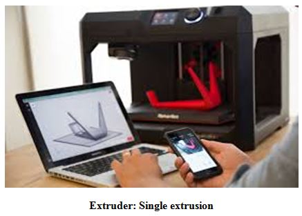
3D Printing is a name associated with a form of manufacturing called additive manufacturing. Unlike traditional manufacturing methods, 3D printers don’t cut away, bend, or deform a raw stock of material into the desired shape. Instead they build up objects by selectively applying material in layers. This is done without the need for jigs, fixtures, dies, or molds. The additive process of 3D printing allows for the “free” fabrication of complex geometry.

Objectives

  • The 3D printer aims to facilitate learning by developing a technological advantage in various subject matter.
  • The goal of the 3D printer is to create a visual model to enhance the learning experience of the content being delivered.
  • Students will be able to manipulate the printer to create a product servicing multiple interdisciplinary objectives.

Scope

  • It is predicted by some additive manufacturing advocates that this technological development will change the nature of commerce, because end users will be able to do much of their own manufacturing rather than engaging in trade to buy products from other people and corporations.
  • 3D printers capable of outputting in colour and multiple materials already exist and will continue to improve to a point where functional (electronic) products will be able to be output.
  • With effects on energy use, waste reduction, customization, product availability, medicine, art, construction and sciences, 3D printing will change the manufacturing world